Closed Loop Control Simulation- Spring 2023

COURSE: ELECTROMECHANICAL DESIGN [ME360]
The goal of the assignment was to simulate a multibody dynamic system coupled to a flexible structure using finite element analysis and motion analysis in Solidworks. The physical system to be modeled is neoprene rubber attached to the end of a flexible steel beam in contact with a cylindrical rotating shaft running at constant speed, seen in the image on the left. The rubber piece experiences stick-slip friction behavior, causing a squeaking sound as both the rubber and the steel beam supporting it vibrate.
The learning objectives were to determine the effects of rotation-induced friction forces on the vibration of flexible structural components and implement a closed-loop control system. The project involves three main deliverables: a multibody dynamic model, a finite element model of a prismatic beam, and vibration analysis.
Deliverable 1:
Video of Motion Simulation
Motion Simulation Setup
The first deliverable is to simulate the stick-slip behavior of rubber on the shaft using a motion study in Solidworks. The rubber piece is assumed to be a cube that is constrained to move linearly and tangentially to the shaft. One flat face of the block is held in contact with the shaft by an applied normal force, which can be modified as needed. A spring applies a tangential force that simulates the stiffness of the steel beam and prevents the block from sliding away. The effective spring constant is found using FEA on the beam in deliverable 2. A motor rotates the shaft at a constant speed.
Motion Simulation Setup
Video of Motion Simulation
Motion Simulation Setup

The spring is connected to the block and a fixed point directly below it.
Video of Motion Simulation
Video of Motion Simulation
Video of Motion Simulation
In this video the shaft is rotating clockwise at 20 rpm. The block moves up due to the friction until the spring force overcomes the friction force and the block slips down, resulting in oscillatory motion.
Deliverable 2:
FEA Displacement results
FEA Displacement results
The goal of deliverable 2 is to determine the tip stiffness of a cantilevered steel beam from finite element analysis and compare it to the theoretical value. The beam is fixed on one end and a force imitating the weight of the block is applied to the other end. The model is solved to determine the deflection of the beam under load, from which the stiffness of the beam can be calculated.
FEA Displacement results
FEA Displacement results
FEA Displacement results

The displacement of the beam is shown true to scale, with the back end fixed and the front end most significantly displaced.
calculations
FEA Displacement results
Deliverable 3:

The experimental k value found from the FEA results is 98.6% accurate compared to the theoretical value.
Deliverable 3:
Beam midpoint vibration
Deliverable 3:
For deliverable 3, a simulation study of the vibration of the beam is created using a finite element model and a time-varying force. In the motion model previously used, a plot of the friction force between the block and the shaft is imported as the curve defining the time-varying force on the end of the beam in the simulation study. A plot of the vibration of the midpoint of the beam vs time is created. A Fast Fourier Transform on the vibration data, computed in Matlab, reveals the frequency of the beam from the noisy data.
Beam midpoint vibration
Beam midpoint vibration
Beam midpoint vibration

The vibration of the midpoint of the beam is plotted over time while the shaft rotates at 360 deg/s.
FFT of Beam midpoint Vibration
Beam midpoint vibration
Beam midpoint vibration
The FFT of the vibration data at 360 deg/s gives the frequency of vibration of the beam's midpoint as 23 Hz.
Automated Typist- Spring 2023
COURSE: ELECTROMECHANICAL DESIGN [ME360]
The assignment for this group project was to design and create a cartesian motion system with more than 2 degrees of freedom. We chose to build a system that could type on a keyboard based on the user's input speech. The project was challenging, and we hit many obstacles including 3D print failures and coding errors. However, we were ultimately able to reach all of our original goals and even incorporated real-time speech-to-text instead of using pre-recorded audio files.
The system is composed of 3 stepper motors with pulleys and belts to control the forward/backward and side-to-side motion of the stylus. A fourth stepper motor with a pulley moves the stylus up and down by gripping the teeth of a 3D-printed fixture that runs down the length of the stylus. The motors and pulleys are fixed to carriages that are also 3D printed. The stylus was purchased separately and has a rubber tip so that the keys are not damaged.
The stepper motors are wired to an MKS Arduino Mega and controlled with G-code commands sent from Matlab. We measured the coordinates of each key and wrote code to turn strings into G-code commands for each letter's coordinate. We set up text-to-speech code by connecting to a Google Cloud API key. The Matlab Audio Toolbox allows us to record user's speech, which is then transcribed and used as the input for the stepper motor control.

CAD Model- carriage
CAD Model- carriage
CAD Model- carriage

This is one of the carriages we designed to slide along the bottom aluminum beam. The foot fits inside the rut on top of the aluminum beam and the side supports prevent the carriage from rotating to allow for smooth sliding. It has two slots for the two ends of the belt, one of which is angled to allow for easier assembly. It supports a beam and pulley perpendicular to the beam it slides on.
CAD drawing
CAD Model- carriage
CAD Model- carriage

This drawing shows the top and front views of all the components assembled in Onshape. The assembly includes both designed components and imported files of the motors, pulleys, and aluminum beams.
PVC Gasket- Spring 2023

Course: Electromechanical Design [ME360]
The goal of this assignment was to make a PVC gasket that fits onto the pins of an aluminum block, pictured left, without obstructing any of its features. I used a caliper to measure the dimensions of all features, fillets, and chamfers within 0.005" of the nominal values. This tolerance must be held so the gasket fits over the aluminum block correctly and creates a tight seal. To determine the diameter of the through holes for the screws, I looked at a clearance hole chart and used the "free fit" diameter for 10-32 screws. For the pin holes, I added 0.005" to the measured diameter to ensure that the gasket slips relatively easily onto the pins. Based on my hand-drawn sketch, I then developed a CAD model in Solidworks. I used GibbsCAM to convert the CAD file into G-Code. In GibbsCAM, I contoured the features to define the tool path. Finally, I machined the gasket on a CNC mill and deburred all edges.
Dimensioned Sketch
Dimensioned Sketch
Dimensioned Sketch
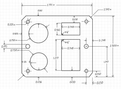
In the hand-drawn sketch above, all necessary dimensions are included without being redundant.
CAD Model
Dimensioned Sketch
Dimensioned Sketch

I imported the CAD model into GibbsCAM, loaded the G-Code file onto the CNC mill, set up the stock material inside the mill, then ran the program to machine the final part pictured to the right.
Completed Gasket
Dimensioned Sketch
Completed Gasket

In the image above, the finished gasket is placed on top of the aluminum block. The gasket fits over the pins easily and without a large gap.
Fidget Toy- Fall 2022
COURSE: MANUFACTURING PROCESSES [ME358]
COURSE: MANUFACTURING PROCESSES [ME358]
COURSE: MANUFACTURING PROCESSES [ME358]
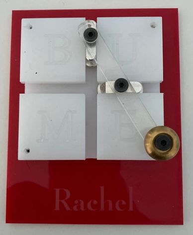
This project was completed throughout the semester as we learned various manufacturing processes. Each component of the project was machined differently to give students experience with multiple processes and equipment. The red acrylic back was laser cut and etched. The brass handle was turned on a manual lathe. On the pre-cut arm and white base, I drilled and tapped the three necessary holes. On the base I also used a manual mill to machine the crossed slots. The feet of the toy (not pictured) were made on an injection molding machine which I did not operate but was able to closely observe.
Completed toy
COURSE: MANUFACTURING PROCESSES [ME358]
COURSE: MANUFACTURING PROCESSES [ME358]
Video
COURSE: MANUFACTURING PROCESSES [ME358]
Video
Circuit Schematic
Circuit Schematic
Circuit Schematic

Before building the circuit, I designed it based on the concepts I had learned in class. This is the final schematic after troubleshooting some issues we had with the frequency filters.
Test Video
Circuit Schematic
Circuit Schematic
We tested our circuit by playing music and seeing how the red LED lights up only to the bass and the green LED lights up to the voice and other instruments within the treble range.
Flood Monitor- Fall 2021
COURSE: INTRODUCTION TO ENGINEERING DESIGN [EK210]
In this class, I was placed in a group of four people and given the task of designing and prototyping a flood detector that alerts city officials of rising water levels. The product is to be attached to lamp posts throughout Boston's Seaport district. We spoke with a professor who acted as a government official so we could gauge the needs of the city and what features to include in our product. We determined that some of our most important objectives were to accurately measure water levels, send timely alerts within a 10 mile radius, survive harsh outdoor conditions, and keep our budget below $400. Because the goal was to install many throughout the area, it was also important that the device be easily installed and repaired, be unobtrusive, and require little maintenance. We used a morph chart to compare means of achieving each feature. To read water levels, we decided on an ultrasonic sensor because of its low cost and long-distance capabilities. Because of the wide range of the sensor, we implemented a PVC pipe to direct the ultrasonic waves to a smaller area and increase the accuracy. To increase the life of the device, we added a floater switch at the base of the pipe. It only completes the circuit when water levels are abnormally high, preserving the battery life significantly. We determined that the best way to send a timely alert is via text or email messaging. We used an ESP8266 WiFi module that can wirelessly connect to the Internet. Through a free online service, we programmed the module to send an email or text to the desired recipient. Ultimately, we achieved most of our goals for the working prototype after much brainstorming, planning, and troubleshooting.

Detector Box
Entire Prototype
Entire Prototype

In our prototype, we built a the box out of clear acrylic so that the inside components were visible. We laser cut the sides of the box from the acrylic stock, then used a silicone sealant to construct the box in a waterproof manner. To keep the electric components inside the box protected from water splashing up through the pipe, we did not cut a hole in the box and instead inserted the ultrasonic sensor directly inside the top of the pipe. The few wires that need to be connected to the sensor and the floater switch are threaded through a small hole that is sealed with silicone.
Entire Prototype
Entire Prototype
Entire Prototype

This view of the prototype shows how the pipe is connected to the bottom of the box and is meant to extend down the length of the lamp post until the base reaches close to ground level. The black metal hook is to secure it to the lamp post in a way that is durable but can also be easily disassembled for maintenance.
Test Video
Test Video
The video to the right shows a successful test of the prototype. When we first inserted the bottom end of the pipe in the water, the ultrasonic sensor read the height of the water, and an email was sent within one minute reporting the height and a warning about waters rising. When more water was added to the beaker, another email was sent with the updated water height.
The technical report of the project can be downloaded below.
Test Video
Test Video
Test Video
Temperature Monitor- Spring 2021

Course: Hands-On Engineering [EK131]
In this introductory engineering course, I built a temperature monitor that displays the temperature of a user's home and alerts them of temperatures above or below their desired range. I first used drafting tools to take dimensions of a plastic box and recreate it as a CAD model in Onshape. Then I prepared the model to be 3D printed by converting it to an STL file and manipulating the printer settings. Because of the high risk of Covid at the time, our university's machine shop was closed so instead of 3D printing the box, I cut it out and assembled it from cardboard. The next step in the process was to design the circuitry and program an Arduino Uno. Finally, I assembled all components and tested the product.
Cad Model- Isometric View
Cad Model- Isometric View
Cad Model- Isometric View

After building a model of the plastic box, I assembled the necessary components inside. The LCD screen, buzzer, LEDs, and thermistor had to be visible from outside the box. I placed the breadboard, battery holder, and Arduino Uno inside the box in a manner that allowed the wiring to be organized. I designed the battery holder, which can be seen more clearly in the technical report, to both secure the battery while the box is hung on the wall and to allow the battery to be changed with ease.
Cad Model- Top View
Cad Model- Isometric View
Cad Model- Isometric View

This image provides another view of how the inner components are organized.
The Wiring
Completed Product
Completed Product
I built this schematic to plan the wiring and organize the electrical components. I utilized a thermistor to detect the temperature, an alphanumeric LCD to display the temperature readings, an on/off switch, a green LED to indicate power, and a red LED plus a buzzer to indicate out-of-range temperatures. The real wiring can be seen in the image to the right. I had to use the provided cables which were long and difficult to organize, but I grouped them the best I could with electrical tape and they were able to fit inside the box easily with the lid closed.
Completed Product
Completed Product
Completed Product

The completed temperature monitor was successful. I tested it by using a hair dryer to heat the air around the box to higher than the desired range. The red LED blinked and the buzzer sounded. The same goal was reached when the room temperature was below the inputted range. The LCD screen displayed temperatures accurately within 5° of the temperatures reported on a different temperature gauge.